2025 · Question 11 · Section B
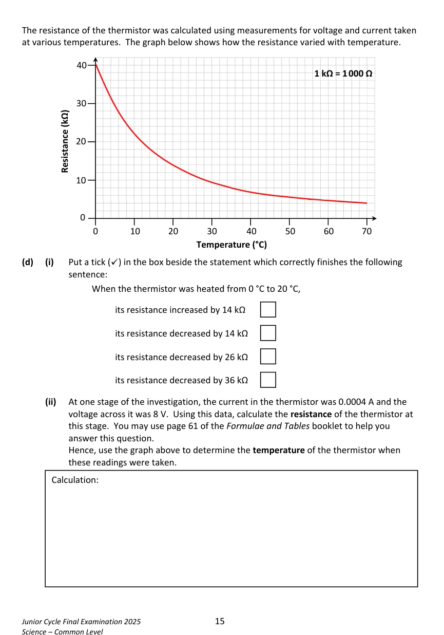
LED and thermistor circuits
Electricity · Graphs · Investigations
Mixed topics: some parts assess other topics. The whole question is preserved.
Open in original paper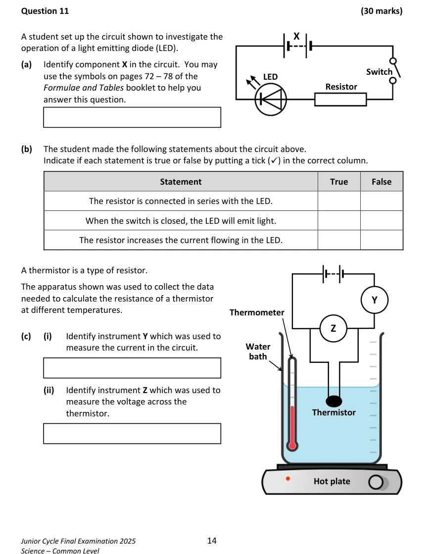
Show solutions
2025 · Question 11 · Worked solution
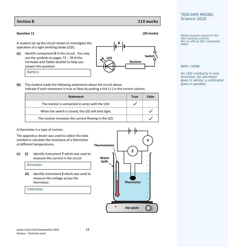
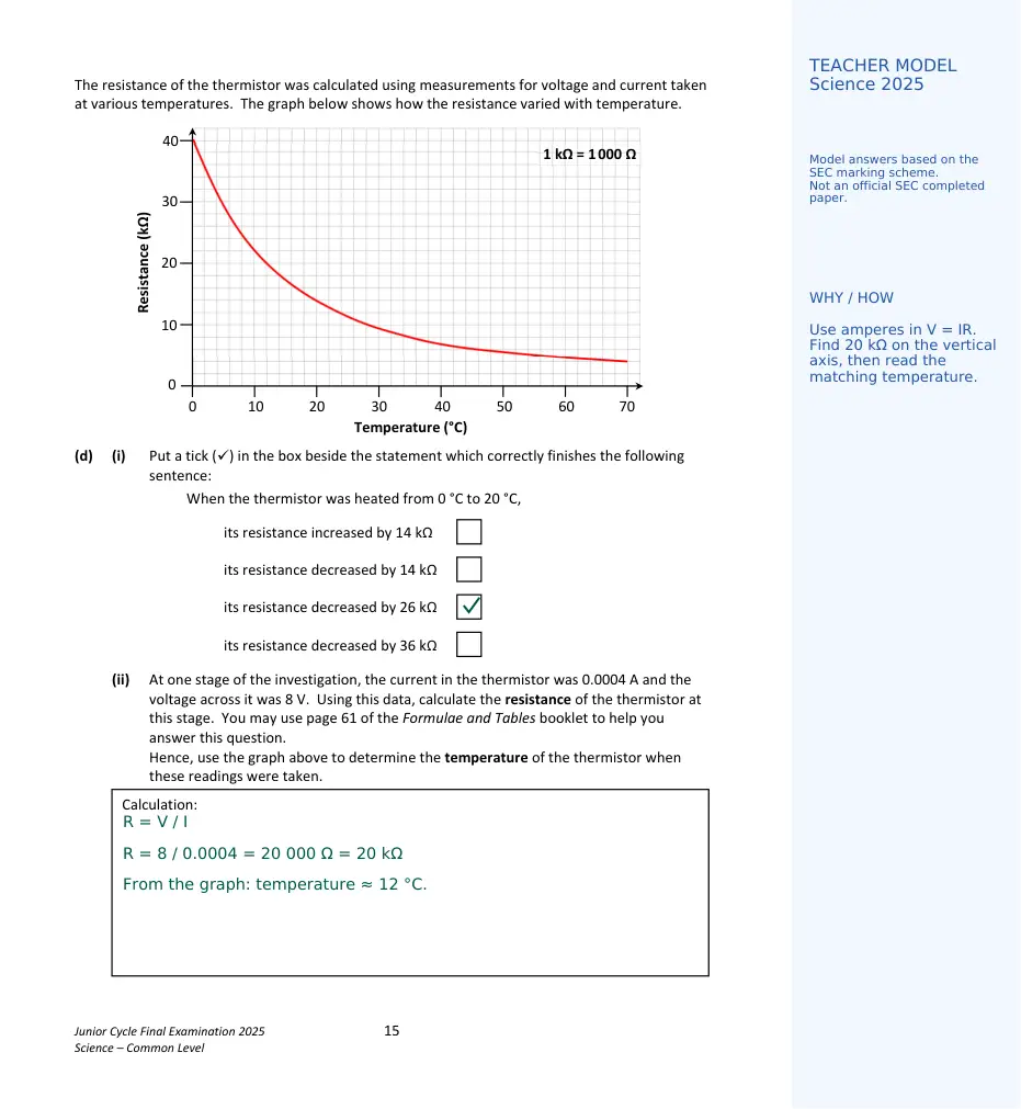
Answers are placed on the original paper, with diagram labels and blue teaching notes alongside. Teacher-completed model based on the SEC marking scheme. Added explanations are teaching notes; no answer mark allocations have been added.
Text version and further explanations
Study solution adapted from SEC marking scheme with added explanation. Teaching guidance, not an official SEC worked answer.
Working and answers are in dark text. Blue “Why this works” notes explain the key ideas beside the relevant step. On a phone, the note appears directly underneath.
a) Battery.
b) In order: true; false; false. The LED is connected in the non-conducting direction; the resistor limits rather than increases current.
c) i) Ammeter. ii) Voltmeter.
d) i) Resistance decreases by 26 kΩ. ii) Convert 400 µA to 0.0004 A. Resistance = 8 ÷ 0.0004 = 20 000 Ω = 20 kΩ. Reading the graph gives 12 °C.
Teacher sign-in and homework controls
Questions and worked solutions are open to everyone. Teachers can sign in to assign homework.
Join a class or manage your homework →